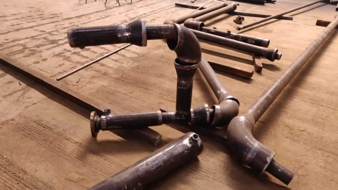
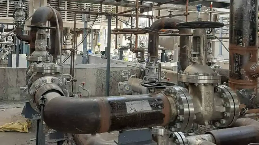
Where we need to transport high dense and high viscous fluid from one point to another point. This becomes difficult to maintain the flowability of fluid because of its highly viscous nature and high density. here comes the role of jacket piping, Processing, and transportation system of this type of piping network helps to maintain a certain required temperature that makes the fluid more flowable.
When it is mandatory to maintain a certain temperature of fluid throughout the transportation system, we can jacket piping. Because of Its jacketed layer, fluid flowing through the core pipe doesn’t lose its temperature and transportation becomes easy. In the Sulpher processing plant or Manufacturing plant of Vegetable oil, the issue regarding of transportation of material is really a serious concern. To resolve that Engineers come up with the idea of Jacket Piping.
Here in this Article on Jacket Piping, You will learn:
- What is Jacket piping and how this works?
- What are the types of jacket piping?
- General Requirement and SOP of jacketed Piping Fabrication.
- SOP for Jacket Piping Erection.
- Design Consideration of jacket Piping System
More to Gain: What is Piping? How piping is Different from Plumbing?
Table of Contents
What is Jacketed Piping?
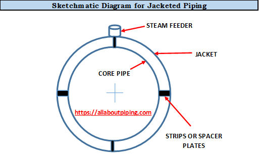
The jacketed piping system consists of two layers of Pipe traveling parallelly in which a lesser size of pipe passes through the center of larger size pipe. Jacketed piping has mainly four components that make a difference from a normal piping system. those four components of Jacketed piping are:
- Core: This central pipe of a jacketed piping system that carries fluid from one point to another.
- Jacket: This the essential part of the jacket pipe that carry superheated steam to maintain the temperature of fluid flowing in the core pipe
- Steam Feeder: This is a tapping connection in the Jacket that provides a path for the steam inlet or outlet.
- Strips/Spacer Plate or Guide: In order to maintain concentric parallelity of jacketed piping throughout the network Spacer plate or Guide or Strips are used to weld between both Core and Jacket to support the jacket pipe from being disorientation.
Featured Article: Heat Tracing in Piping: Types, Working, Use, Installation, Comparison
Types of Jacketed Piping
According to the nature jacket pipe installation over core pipe, there are mainly two types of Jacket Piping.
- Continuous Jacketing: In this type of piping all straight lengths of pipe including flanges, fittings, valves, and branch connections are fully jacketed.
- Discontinuous Jacketing: This type of Jacket pipe consists of jacketing of only straight lengths of pipe. Here Branch connections, Fittings, and Valves are not jacketed.
General Requirements of Jacketed Piping
According to the requirement of type jacketing for some specific processing plant selection of the type of jacketing shall be in accordance with the approved drawing. A steam jacket pipe consists of a process line that passes through the contra of a large diameter steam line. The nominal sizes of the inner pipe (core) and outer pipe (jacket) in inches are as given in the table below:
Table for Jacket pipe size, Core pipe size and Steam feeder
| Core Pipe Size (in Inches) | Jacket Pipe Size (in Inches) | Steam Feeder Size (in Inches) |
|---|---|---|
| 0.75 | 1.5 | 0.5 |
| 1 | 2 | 0.5 |
| 1.5 | 3 | 0.5 |
| 2 | 3 | 0.5 |
| 4 | 6 | 0.75 |
| 6 | 8 | 0.75 |
| 8 | 10 | 0.75 |
| 10 | 12 | 0.75 |
Some of the typical requirements of jacket piping are as below:
- The material specification of the Process line (inner core) shall be as per P&ID and approved Piping isometric drawing.
- Material specification of the jacket shall be carbon steel when the jacketing is done with LP Steam.
- Material for inlet lead line, jump overs, and outlet lines shall also be carbon steel.
- The material grade of the guide strips/ spacers and wear plate shall be the same as the core pipe.
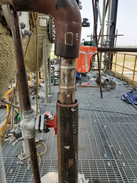
- If the material specification of the core pipe is stainless steel, compatible welding consumable (Eg: SS309) shall be selected to weld the Carbon Steel jacket with the Stainless Steel core pipe.
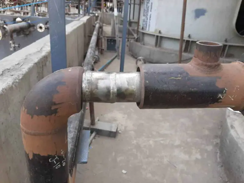
- Long radius elbows (1.5D) shall be used in core piping and short radius elbows (1D) shall be used in jacket piping in order to expose the weld joint of the core pipe with an elbow after inserting the jacket pipe and elbows.
- Inlet and outlet nozzle for steam should be given as per standard.
Featured Article: An Overview on Different type of piping drawing used in Piping Project Construction
jacketed Piping Fabrication Procedure
Above mentioned two types of Jacketed Piping, have some similar yet some different procedures for fabrication. In this pipe spool fabrication procedure, we have to look for jacketing of Fittings too in continuous jacket piping. In discontinuous jacket piping, only straight lengths are being jacketed. So, SOP for jacketed piping fabrication details for both types of jacketed piping is as below:
Flanged Core jacket piping with Fittings (continuous jacket piping)
For the fabrication of continuous jacketed piping fabrication all details are summarised in the following steps:
- Weld guide strips/ spacers on core pipe
- Weld wear plates on core pipe Make holes on the jacket pipe ends to provide steam nozzles before inserting into core pipe spool
- Weld inlet and outlet steam nozzles on the holes of jacket pipes Sequentially insert the jacket pipe and its fittings along with end caps or check
- plates into the core pipe during fit-up of core pipe with fittings such as Elbows and Reducers
- Complete the welding of fittings with core pipe and weld the flanges at both ends of core pipe then
- Perform NDE and Hydro test of core pipe as per requirement Weld end caps with core pipe and jacket ends
- Perform NDE and Hydro test of jacket pipe as per requirement
- If equal or unequal Tee exist in the core piping, jacket Tee must be cut into two half and shall be fit up after welding and hydro testing of core piping
- If a branch or small-bore tapping exist in the core piping, a hole on the jacket pipe shall be provided appropriately prior to insertion and a jacketing branch shall be provided once welding and hydro test of the core piping are completed Jacketed valve shall be procured in case of requirement of valves in the circuit/ line.
- Drain the test water completely and send the spool for erection after painting, if applicable
Flanged Core Jacket Piping without Fittings (discontinuous jacket piping)
- Weld flange with core pipe at one end. In the case of fully jacketing, reducing flanges shall be used.
- Weld guide strips/ spacers on core pipe Weld wear plates on core pipe
- Make holes on the jacket pipe end to provide steam nozzles before inserting the core pipe spool
- Weld inlet and outlet steam nozzles on the holes of jacket pipe Slide jacket pipe over core pipe along with end caps or check plates
- Weld remaining end flange to other ends of core pipe
- Perform NDE and Hydro test of core pipe as per requirement In case of Partial jacketing, weld end caps with core pipe and jacket ends.
- In case of full jacketing, weld the jacket directly with the reducing flange. Perform NDE and Hydro test of jacket pipe as per requirement
- Drain the test water completely and send the spool for erection after painting, if applicable.
Use of Guide Strips/ Spacers and Wear Plate in Jacket Piping
In order to ensure the uniformity of the jacket annulus, Guide strips/ Spacers are provided in accordance with the following requirements:
- Minimum three guide strips shall be welded at 120deg apart around the circumference of the core pipe.
- Distance between spacer groups and jacket end termination shall be maintained as specified in the table of the schematic diagram.
- Spacers or jacket end termination shall be placed within 1.2 meters (4 feet) of tangent point of elbows or center point of concentric fittings.
- At least one spacer group or jacket end termination shall be provided for each straight run of pipe.
Wear plate shall be welded with the core pipe where the steam entry is taking place to protect the core pipe from the direct impact of the steam flow. The size of the wear plate shall be selected considering the steam nozzle size. The thickness of the wear plate shall be 3mm or 4mm.
More Resources: What Is RF Pad? How To Calculate Reinforcement pad dimensions?
SOP for Erection of Jacketed Piping Spools
- A steam jacket circuit is formed by a number of jacket sections (pipe, fittings, valves, etc.) which are connected in series by jump-overs. Each steam jacket circuit has its own valved steam supply and condensate drains through steam traps.
- In principle, the steam inlet pipe must be connected to the uppermost point of the circuit.
- Jump overs connect the lowest tapping at the jacket end over a welded or flanged joint to the top (or side) tapping in the adjoining jacketed section for horizontal piping. The steam and condensate are carried together from one section through the jump over to the next section. In the case of flanged joints, the jump over shall be provided with a breakup flange. The inlet & outlet to steam jacket shall be 180 deg apart.
- The maximum number of jacketed sections included in one circuit depends on the layout, type of fittings or valves, size, insulations, etc. A straight run of pipe shall have break-up flange joints at every 5Mtr (max.)
- The total length of one circuit shall not exceed 20Mtr in the case of continuous jacketing and 25Mtr in the case of discontinuous jacketing.
- The layout of piping and equipment must be such as to reduce potential congealing to a minimum. Dead-ended and non-circulating piping should be avoided where possible.
- The heating medium shall flow countercurrent to the product flow.
- Jacketed piping should be designed and installed with some slope to facilitate drainage.
- After installation, the entire jacket line shall be pressure tested along with jump over connections. Water shall be completely drained after the test.
Use of Jacketed Piping
Jacketed piping has some of its limited but very important role in processing industries where we need to maintain a certain temperature throughout the transportation of fluid from one point to another. Some of the highlighted examples of the use of jacketed piping are:
- In sulphuric acid plant, for transportation of molten Sulpher through pipes.
- In the oxygen generation unit, for conveying liquid Oxygen, a very low-temperature fluid. Jacket piping used to stop the piping network from getting frost.
- In vegetable oil manufacturing plant, to maintain fluidity throughout piping network.
- In pipeline networks of passing through cold areas.
- In Bulk career merchant ship, To stop choking of pipe because of extreme cold temperature.
Design Consideration of jacketed Piping System
Jacketed piping systems are much more complex piping systems than normal standard process piping because of their double-walled piping network. So, these type of piping projects requires some special attention during engineering, designing, and execution phase. there are some considerations that must be taken into account while designing a jacket piping network.
1. Fluid Pressure
The fluid flowing in the core pipe must be operatable at a lower pressure than the fluid flowing in the jacket pipe. This is to ensure that in the event of any unseen failure in process core piping, the product can be contained in the jacket in place of flowing outside of the system.
2. Feeder Port Location
The feeder inlet port location for inlet and outlet varies as per the media chosen for jacket piping, In the case of a Liquid medium of jacket pipe for the system feeder port should be located at the lowest point in the jacket for inlet and at the highest point for the outlet. This is to ensure that the jacket will fully be filled with media before leaving the system.
While in the case of gaseous media like the steam of jacket pipe, the Inlet port of the feeder should be at the highest point and the outlet point at the lowest point for the same reason as liquid media.
3. Slope
A jacket piping system must be installed with some slope required as per density and viscosity of fluid flowing in core pipe to ensure complete drain out of process fluid from core pipe.
4. Fluid Flow direction
The fluid flow direction in the core and jacket pipe must be opposite to each other. This opposite direction of flow gives the advantages of getting the desired rate of cooling or heating the product flowing in the core pipe.
5. Continuity breaks and Joints
A jacketed piping system needs to be designed with a minimum number of break-up flanges and no. of joints. Each break either in jacket pipe or core pipe costs more material to purchase as well as more cost in maintenance of the system.
6. Annular space between Core and Jacket
During design annular space between core pipe and jacket, the pipe needs to optimize to stop product either from solidifying or from scorching the material of the piping system
7. Stress Analysis of Piping system
Because of the different operating temperatures and pressure of core and jacket pipe, stress can be developed in the system that causes the failure of the piping network. For this reason, it is considered to have a good practice of stress analysis of jacketed piping.
8. System components and Layout
At last, during the designing of the jacketed piping network following must take into consideration:
- Thermal difference and expansion between the core pipe material and jacket pipe material.
- Types of section connectors to be used.
- Internal supports or guide strips installed between jacket and core pipe.
- Any requirement of turbulence mechanism in the pipe such as flow disruptors, fins, and wraps.
- The potential of corrosion on both core and jacket side of the pipe.
Conclusion
Jacket piping is a special kind of piping system that helps for transportation of fluid in a pipe with maintaining a certain temperature throughout the network. Sum up of complete article is as pointed:
- There are two types of jacketed Pipes: a. Continuous jacketed piping and b. Discontinuous jacketed piping.
- The inner pipe of the jacketed piping system is called the core while the outer one is called the jacket.
- In the Jacket pipe, there are some media either in liquid or gaseous form to maintain temperature throughout the network.
- SOP for continuous and discontinuous jacket piping fabrication is different.
- A metal stripe or guide is used to support the jacket pipe from the core pipe.
- Some most essential points of design must take into account while designing a jacketed piping network as discussed above.
